This tutorial is for these with some DIY expertise, although superior newbies could discover it a enjoyable problem. Also, skilled customers would possibly discover it enjoyable to set this up for newbies to study from. To make this board with out the SparkFun IoT Starter Kit with Blynk Board, you will want sensors and different elements to finish the built-in tasks. For occasion, the SparkFun Blynk Board comes with onboard WS2812 RGB LED, so you will want a similar module to make tasks utilizing the system. You can buy the elements individually from Sparkfun.
I manage workshops in my local people to introduce individuals to open supply platforms equivalent to Arduino and Raspberry Pi. With all the thrill across the Internet of Things today, everybody desires to start out tinkering and prototyping. The lovers are normally designers, internet builders, or college students, and most need to get going with little coding.
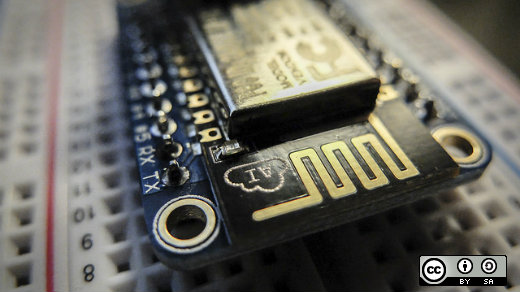
ESP8266-based Blynk Boards include preloaded tasks and are perfect for introducing Internet of Things and primary electronics ideas.
About the
The ESP8266 is a superb chip with built-in WiFi. It was initially used with Arduino boards to WiFi-enable tasks however quickly grew to become an inexpensive standalone Arduino-compatible improvement board. It is available in many shapes and varieties and is most well-known in improvement boards equivalent to NodeMcu, Adafruit HUZZAH, or the SparkFun ESP8266 Thing.
David Egts wrote this terrific article about the ESP8266.
While the ESP8266 is nice open supply for getting began with the Internet of Things, Blynk is a perfect platform to manage Arduino, Raspberry Pi, and the like over the Internet. Essentially, Blynk contains three elements: a Blynk app for the smartphone, the Blynk server, and Blynk library (firmware), which is suitable with quite a lot of makers’ .
Both the Blynk server and Blynk library are open supply, whereas the Blynk app is obtainable free for iOS and Android. The Blynk app lets you construct a graphic interface on your IoT challenge by merely dragging and dropping widgets. Blynk contains widgets equivalent to LCD show, Joystick, and Buttons so you can begin hacking away with simply an IoT improvement board.
Blynk partnered with SparkFun to create the SparkFun Blynk Board primarily based on the ESP8266. It comes totally programmed and contains greater than ten pre-loaded Blynk tasks. The SparkFun IoT Starter Kit with Blynk Board is a stable introduction to the world of Internet of Things (IoT) know-how with no tough programming.
If you are like me and have a number of ESP8266-based improvement boards mendacity round, you should utilize the firmware and switch them into DIY Blynk Boards. This could be very best for working boot camps or workshops utilizing present boards. You’ll nonetheless want sensors and different elements to have the ability to full the built-in tasks. For occasion, the SparkFun Blynk Board comes with onboard WS2812 RGB LED, so you will want the same module to make tasks utilizing the system.
Making a DIY Blynk Board
Gather the gear
- An ESP8266-based improvement board equivalent to NodeMCU, Wemos D1, Sparkfun ESP8266 Thing, and so on.
- Computer with Arduino IDE and correct drivers for improvement board
You ought to already be capable of flash an Arduino sketch onto the event board. - USB cable to attach board to a pc
- WiFi community
- Smartphone
- An LED for testing
- Blynk app: iOS and Android
Before going any additional, obtain the app to your good system.
Install the required libraries
- Open the Arduino IDE
- Go to Sketch –> Include Library –> Manage Libraries
- Search for “blynk”, then set up:
- Install the next extra libraries, utilizing the newest model obtainable:
SparkFun HTU21D:
Adafruit NeoPixel:
SparkFun TSL2561:
Flashing the ESP8266 board with Blynk Board firmware
- Download the Blynk Board firmware.
Extract the content material of the zip file:
- Open any of the .ino recordsdata, which is able to open the Arduino IDE with a number of tabs:
- Scroll down on the BlynkBoard_Core_Firmware tab and uncomment the road:
//#outline DEBUG_ENABLEDComment the road:
#outline SELF_TEST_ENABLED - Select the suitable board (I’m utilizing NodeMCU):
- Verify the sketch. The construct must be profitable.
- Connect your board to the pc by way of USB cable and add the sketch.
The board is now flashed with BlynkBoard firmware.
Provisioning your DIY Blynk Board
In the provisioning course of, we’ll use a smartphone, laptop computer, or pc to attach immediately (over WiFi) to the Blynk Board. Once related, your good system will ship the required knowledge and inform the Blynk Board to hook up with your Internet-connected wi-fi community and Blynk.
The Blynk Board is initially configured to function as a WiFi entry level (abbreviated “AP,” form of like a router). A smartphone or WiFi-enabled pc can briefly connect with the Blynk Board, and utilizing both the Blynk app or a browser, ship the entire obligatory data over to it. After the Blynk Board receives that data, it’s going to transition from AP to WiFi system and connect with your WiFi community. The AP has SSID within the format BlynkMe-XXXX:
Note: The SparkFun Blynk Board has a built-in RGB LED. When powered on, it blinks with a singular sequence (randomly allotted) of 4 colours, together with both crimson, inexperienced, blue, purple, or yellow, with a protracted cease in between. If you will have a WS2812 RGB LED, you may join it to Pin four. In my case, the LED would blink crimson, crimson, yellow, after which crimson.
Follow one of many different provisioning strategies in Sparkfun’s Getting Started with the SparkFun Blynk Board tutorial.
Testing the board
(Source: SparkFun tutorials)
Blynk setup
1. Make positive your challenge isn’t working – the upper-right icon must be a triangular play button.
2. Touch anyplace within the clean grey challenge house. A toolbox ought to open up on the appropriate facet with your entire widgets to select from.
three. Select the Button widget by tapping it. You’ll discover it on the prime of the “Controllers” listing.
four. Tap and maintain the button widget to tug it anyplace inside the challenge house. You’ve obtained numerous room to work with proper now.
5. Touch the Button Widget to carry up the settings web page, and modify these values:
a. Name: “LED” – While the widget is a button, we’ll be utilizing it to manage an LED.
b. Output: 5 – within the “Digital” listing.
c. Color: Click the crimson circle to vary the colour of the button. Try blue, since we’re toggling a blue LED.
d. Mode: Use “Switch” mode.
6. Confirm the settings:
If you are utilizing an Android, hit the again arrow within the upper-left nook
If you are utilizing an iOS system, hit the OK button.
Adding an offboard LED
Wire the LED as proven within the diagram under. The LED’s optimistic pin (the longer leg) must be related to GPIO Pin quantity 5. Accordingly, on the NodeMCU GPIO 5 is Pin D1. Identify the right pin on your board by referring to its pinout reference. The different LED pin must be related to a floor pin (“GND”).
Blynk run
Now that the button is all configured within the Blynk app and the LED is correctly wired to the board, run the challenge by tapping the Play button within the upper-right nook of the display in Blynk app.
Once the challenge is working, faucet the Button widget. When the widget is about to ON, the LED must also activate.
Congrats! You have efficiently made a DIY Blynk Board. You can now observe the above steps for every other ESP8266-based boards you will have, and kit up for introducing IoT to lovers in your neighborhood.